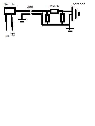
Receiver circuits are designed to have a specific impedance, usally 50Ohm. In order to maximize received power, the antenna impdance is matched into 50 Ohm. This is done with a matching circuit on the antenna side of the transmission line, to avoid losses due to standing waves on the line itself.
To keep designs simple, the transmitter will reuse transmission line and antenna of the receive path. Receiver and transmitter are then either multiplexed through a switch in TDD systems, or coupled together in case of FDD sytems. The switch or coupler can be located inside the radio chip or module. This results in the transmitter "seeing" a 50 Ohm impdeance when "looking" into the transmission line. Transistor-based power amplifiers of transmit circuits have output impedances around 1 Ohm. If the transmission line is short compared to the wavelength, matching is not necessary as standing waves waves will not be significant. If the transmission line is more than 10 % of the wavelenth in length the transmitter should be matched to come closer to 50 Ohm on the transmitter side of the transmission line.
